Hey there,
It’s Robin from CFD Engine & I thought I’d share a way to calculate projected areas in ParaView this week 🤓
It’s one of those fiddly little jobs that you might not do very often. But if (like me) you have clients who have a thing for drag coefficients, you might end up doing it more often than you’d like.
A bit niche? Perhaps, but if you need the projected area of a complex geometry (& your CAD package won’t do it) then here’s how you can get a decent estimate out of ParaView.
Steps
Take a screenshot
- Read the object(s) of interest into ParaView
- Set the required view
- turn perspective off by setting the viewport to 2D
- turn off the little orientation axis (unless you want the projected area of that too)
- Save a screenshot in PNG format
- make sure the
Transparent backgroundbox is checked - higher resolution = better area estimate
- make sure the
Estimate the area
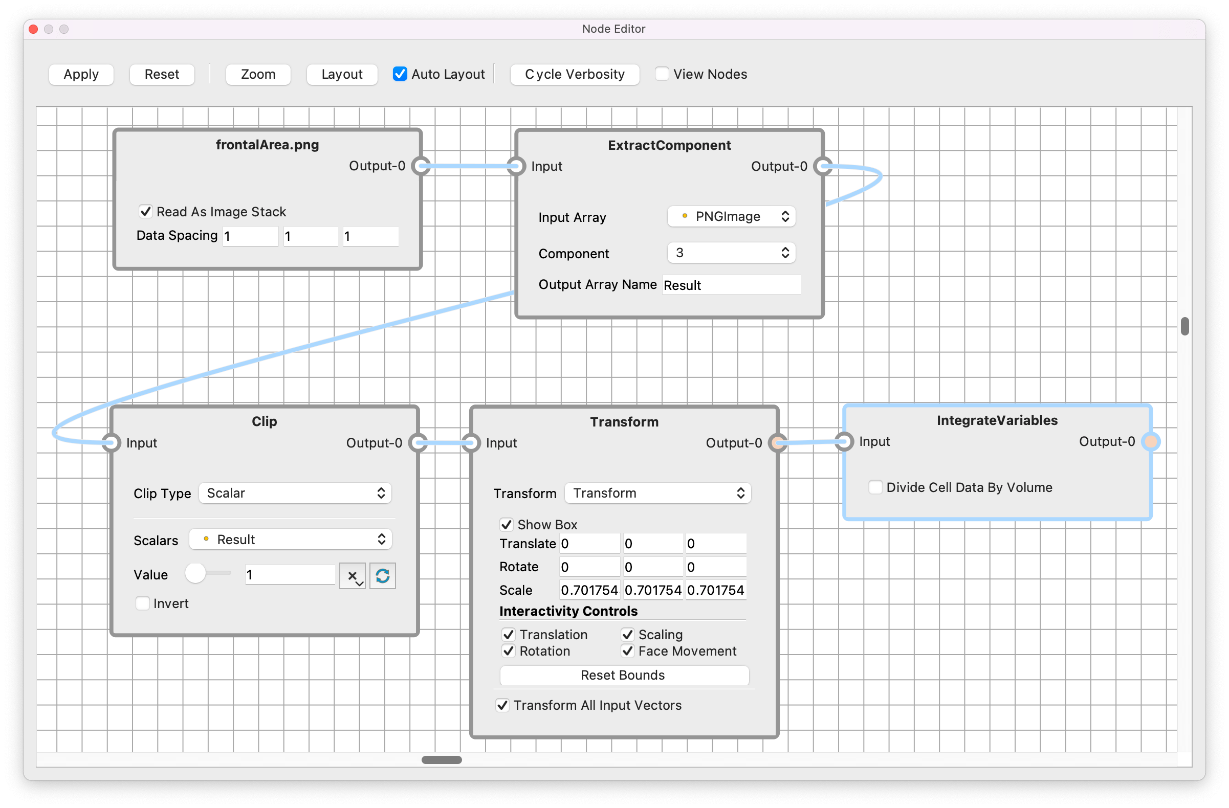
That was the prep work, here’s the pipeline to estimate the area (click for a bigger version).

I’ve shown it as a node network, but you don’t need to use the node editor to build it – it’s just a neat way to show the filters, the settings & how it’s all wired up.
In case the nodes make no sense, it goes a little something like this:
- Read your new PNG file back into ParaView
- Apply the
Extract Componentfilter & extract component3– this is the transparency (alpha) channel of the PNG & we’ll use it to delete the background. - Apply a
Clipfilter, set the type toScalar, select theResultfield from the previous step & set the value to1. - You should be left with the silhouette of your object, but it’s almost certainly the wrong size, so we’ll use the
Transformfilter to correct that.- The
Informationtab will show you the current dimensions of the silhouette, grab the width (or height) & grab the same info from your input geometry. - Make sure to use the right dimensions, the PNG always lies on the XY plane.
- Determine the scaling factor between your two values & use it in the
Scalesection of yourTransformfilter. Click Apply. - Check that the dimensions of the scaled silhouette match those of the input geometry.
- The
- Apply the
Integrate Variablesfilter to calculate the area of the silhouette. This will open up a spreadsheet view with the results & you’ll find theAreaunder theCell Dataattributes 👍
Go further?
It would be pretty easy to turn the above steps into a Python script that you could include in an Allrun, using the calculated area in your forceCoeffs function object (I’d probably not bother, but you could).
You could save the steps as a state a state file (.pvsm) so you don’t have to remember the pipeline (as long as you can remember where you put the state file).
You could even save the steps as a custom filter, so that projected area is only a click away. But you probably don’t do that many projected area calcs & if you do, you’ve already got a better method than this.
I might do an email on ParaView’s custom filters though, they’re actually pretty handy 🤔
The tools you have.
Could this be neater? Yes, but it works pretty well & it’s not as complicated as it might seem.
Give it a go & let me know where you run into trouble.
I’m a big fan of using the tools you already have for little jobs like this. Do you have any similar examples in your process? Drop me a note, I’m always keen to hear how you’re getting things done in CFD 🙏
Until next week, stay safe,
