Hey there 👋
It’s Robin from CFD Engine & we’re exploding things this week 👇

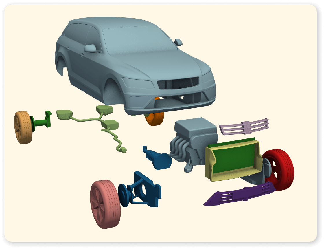
I’m sharing a simple, flexible, scriptable method for creating exploded views in ParaView.
It works at any size, it auto-identifies component parts & the explosion can easily be tweaked to suit your geometry.
It’s not a replacement for a true, artisanal, hand-crafted exploded drawing (& it won’t work well for every geometry) but I’ve found that it’s a useful addition to my standard post-pro.
You’ll need a geometry file with a few parts, a recent version of ParaView & a little patience.
Ready? Let’s go…
Recipe
Here’s the idea…
- Identify all of the discrete parts in an assembly & determine their location.
- Give each of the parts a unique ID, plus a new location vector.
- Use the new vector to warp the parts into their exploded positions.
Here’s the pipeline…
The numbers correspond to the list above.

Here’s some more info…
Compute Connected Surface Properties finds all of the discrete parts in your model, gives them an ID & calculates their volume, area, centroid & validity (which I think means whether they’re closed or not).
It stores this new info as Field Data which can be tricky to access with other filters 🤔 So, we’ll use a couple of lines of Python (via a Programmable Filter) to make the centroid & the part ID available to the rest of the pipeline (as Cell Data).
We can’t Warp using Cell Data so we’ll throw in quick Cell Data to Point Data filter.
We could just leave it at that & use Warp By Vector with the part centroids as an input, but I’ve added an additional Calculator in-between.
The Calculator lets us tweak how our explosion looks, by adding scaling factors to each of our vector components.
For example…
(0.75*Centroid_X*iHat)+(1.1*Centroid_Y*jHat)+(2.2*Centroid_Z*kHat)
…exaggerates the explosion in the Y & Z directions, but tones it down in X – you’ll need to tweak these values to suit your model & its orientation.
Colour it by part ID and you’re done 🙌
Here’s a state file…
You can grab this minimal Python state file if you want to see more detail on the pipeline & take it for a spin.
Save it locally, edit it to read one of your geometry files & open with File > Load State (then cross your fingers & see what happens) 🫣
Your mileage may vary, but it should at least give you something to start playing with.
Gotchas
- the
Compute Connected Surface Propertiesfilter was introduced in ParaView v5.11, so this won’t work in older versions. - the method is based on identifying disconnected parts – the ones that are connected (i.e. they share nodes) won’t be separately identified or exploded.
Over to you
There you have it a semi-automatic way to explode assemblies in ParaView & to create simple plots that reveal the hidden parts in your models.
You might only use this once-per-project, in your final report. Or you might add it to your standard post-pro as a record of each run’s bill of parts. You could even animate it, but let’s not get carried away.
It won’t work for every geometry & it will certainly need tweaking to fit, but let me know if you grab the state file and have a go (&/or what improvements you needed to make) 🫣
Until next week, stay safe,
